Mass analysis – i.e. the separation of bunches or streams of ions according to their individual mass-to-charge (m/z) ratio, is only part of the job of a mass spectrometer. Without some form of accurate and reliable ion detection, everything that happens previously would be pointless. All mass spectrometers, apart from FT-ICR – which by it’s very definition is a combined mass analyser and detector, require an ion detector. The choice of detector depends on the design of the instrument and the type of experiment it was designed to perform. The detector generates a signal from incident ions by either generating secondary electrons, which are further amplified or by inducing a current generated by a moving charge (similar to FT-ICR). The earliest ion detectors (back in the days of Thomson and Aston) consisted of photographic plates located at the end of the mass analyser. All ions of a given m/z would impact at the same place on the photographic plate making a spot. The darkness of the spot was indicative of the intensity of that particular m/z. The most common types of ion detector used in modern instruments are described below
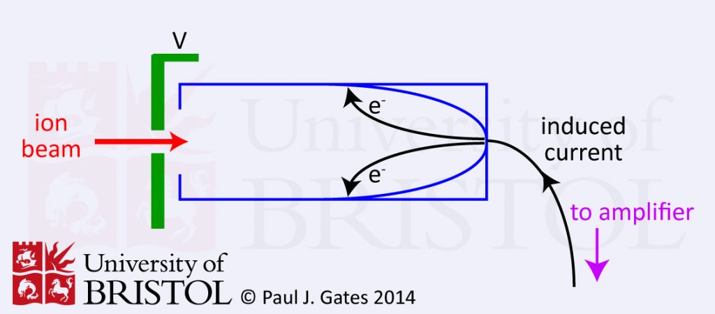
1. Faraday Cup detector (or Cylinder electrode)
The Faraday cup or cylinder electrode detector is very simple. The basic principle is that the incident ion strikes the dynode surface (see figure 1) which emits electrons and induces a current which is amplified and recorded. The dynode electrode is made of a secondary emitting material like CsSb, GaP or BeO. The Faraday cup is a relatively insensitive detector but is very robust. It is ideally suited to isotope analysis and IRMS.
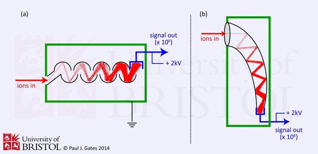
2. Electron Multiplier
Electron multipliers are probably the most common means of detecting ions, especially when positive and negative ions need to be detected on the same instrument. Their are two types (see figure 2) of electron multiplier, but they both work essentially by extending the principles of the Faraday cup. A Faraday cup uses one dynode and as a result produces one level of signal amplification. One type of electron multiplier (figure 2a) has series of dynodes maintained at increasing potentials resulting in a series of amplifications. The other type (the channel multiplier, figure 2b) has a curved (‘horn’ shaped) continuous dynode where amplifications occur through repeated collisions with the dynode surface. In both cases, ions pass the conversion dynode (depending on their charge) and strike the initial amplification dynode surface producing an emission of secondary electrons which are then attracted either to the second dynode, or into the continuous dynode where more secondary electrons are generated in a repeating process ultimately resulting in a cascade of electrons. Typical amplification is of the order of one million to one.
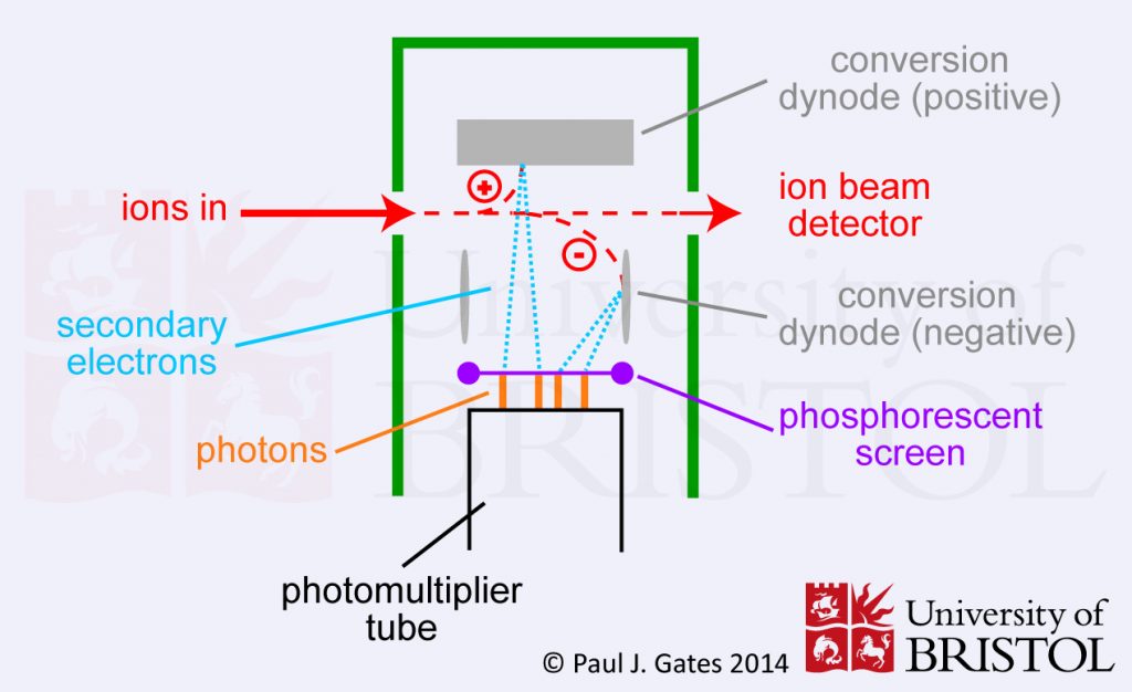
3. Photomultiplier (or Scintillation Counter)
In a photomultiplier (or scintillation counter) the ions initially strike a dynode which results in electron emission. These electrons then strike a phosphorous screen which in turn releases a burst of photons. The photons then pass into the multiplier where amplification occurs in a cascade fashion – much like with the electron multiplier. The main advantage of using photons is that the multiplier can be kept sealed in a vacuum preventing contamination and greatly extending the lifetime of the detector. Photomultipliers are now probably the most common detectors in modern mass spectrometers.